Sponsored Content by NuAireAug 2 2017
When it comes to the life cycle cost of any Biological Safety Cabinet (BSC), the life of a HEPA filter is crucial. The loading capacity of HEPA filters has always been a matter of great concern in the performance and design of a BSC in terms of both replacement cost and lab safety through down time, replacement process, and related costs.
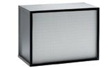
Metal frame HEPA filter. Image credit: NuAire
While the projected HEPA filter loading capacity of BSCs may be brought down with the use of the latest energy efficient motor technologies, it will still be able to meet the NSF/ANSI 49 requirements. The following discussion briefly explains the requirements, what’s changed, why they have changed, and what information is needed from manufacturers to ensure the same loading capacity of HEPA filters.
Some of the latest energy efficient motor designs provide energy savings, which can be offset by frequently substituting the HEPA filters.
History
In August 1973, the National Institutes of Health (NIH) developed the first major BSC specification which included a specification for the loading capacity of filters. The scope and objective of the NIH-03-112 specification was to offer procurement specification for a safety cabinet that contained downflow (which in the past was new), together with inflow to provide protection to both personnel and products.
The safety cabinets would be employed in production or biological research as a tool to regulate airborne contaminants, which are likely to pose some amount of risk hazard to scientific personnel and may also damage the equipment.
The NIH-03-112 specification offered requirements for construction, design, and performance of the original Class II, Type 1 (now type A1/A2) BSCs. Both the fan and motor are covered by section 3.5.6 and 3.5.7.1, respectively. The following requirements specify the performance of fan and motor:
- 3.5.6.3 — Total fan delivery shall fall off no more than 10% as a result of 50% increase in the pressure drop across the filter.
- 3.5.7.3 — The motor shall be sized to operate the fan at a static pressure sufficient to meet the requirements of paragraph 3.5.6.3.
In order to meet the above requirements, the system’s loading capacity was theoretically calculated by plotting a fan curve given by the fan manufacturer together with the motor torque information and operational BSC static pressures given by the motor manufacturer at the so-called airflow set point. The system, in this case, refers to the filters, motor, and fan (with the specific pressure drops) of each BSC.
Until June 1976, the NIH-03-112 specification continued to be the only BSC specification until the Standard 49 Class II (Laminar Flow) Biohazard Cabinetry was implemented by the National Sanitation Foundation (NSF). As the NSF Standard was built on the NIH-03-112 specification, many parts were almost identical, including the motor and fan requirements as mentioned below.
- 4.21.2 — Total air delivery shall fall off no more than 10% as a result of 50% increase in the pressure drop across the filter without readjusting the fan speed control.
- 4.22.1.2 — The motor(s) shall be sized to operate the fan(s) at a static pressure sufficient to meet the requirements of item 4.21.2. Fan motors shall be UL or CSA listed.
In order to meet the aforementioned standard requirements, cabinet manufacturers again submitted a fan curve, providing the appropriate motor and static pressure data to NSF as proof of compliance to the standard requirement.
An NSF task group (motor blower performance task group) was established in the late 1980s to frame a test method to show compliance to the standard against providing theoretical proof of compliance. The present test method was based on the Air Movement and Control Association (AMCA) publication 210, lab-based methods used for testing fans for rating purposes.
The test involves loading the cabinet airflow system and determining the fan’s static pressures per AMCA, and finally measuring the fall off of airflow to establish compliance to the above statement. The 1992 revision of the standard now includes the updated test method, which continues to remain the same even today as per NSF/ANSI 49, Annex A.12, Motor / Blower Performance.
Understanding the basis for the specification
For both the specifications stated above, the performance and design basis involved the use of a forward curved fan and an AC PSC motor. The latter includes an inherent design attribute of increasing motor RPM with higher amounts of resistance (torque), or when employed in a cabinet equipped with a forward curved fan, raises the fan’s RPM with additional static pressure induced by particulate loading on the BSC’s HEPA filters.
Therefore, by specifying a 10% decrease of the overall air delivery from a 50% increase in static pressure ensured that the correct HEPA filters, motor, and fan were designed into the BSC. The so-called 50% increase in static pressure is taken as the baseline and the fan speed control is not readjusted, knowing that the system would get additional capacity from the fan speed control.
The additional capacity, although not specified by NSF, was almost guaranteed with forward curved fans and AC PSC motors. Manufacturers, supplied whatever additional capacity they could provide. This capacity indicates the amount of particulate load that can be applied to the system while sustaining the cabinet airflows at a level that maintains containment.
Most manufacturers used the available forward curved fans, AC PSC motors, and HEPA filters with normal pressure drops, and are generally able to achieve 180% increase in pressure drop or static pressure across the filter with a minimum of 10% decrease in the total air delivery.
This 180% increase in pressure drop became the default industry standard that is now used and published by the majority of manufacturers and is also written in almost all university, governmental, architectural, and private industry BSC specifications.
The specification used today is somehow represented by the following statement:
Cabinet motor/blower shall be positioned so as to create even filter loading, thereby prolonging the life of the HEPA filters, and shall deliver over 50% of the initial HEPA filter static pressure with no more than a 10% decrease of total CFM. Equip each cabinet with a voltage compensating motor speed controller that automatically compensates for voltage changes to maintain constant voltage to motor. Speed controller will permit manual or automatic adjustment to deliver over 180% of the initial HEPA filter static pressure with no more than a 10% decrease of total CFM.
HEPA filter life
The actual life of the HEPA filters will differ considerably for each installation, because the exact filter loading within the field is based on the lab environment in which the BSC is used. For example, if the BSC was deployed in a clean room, the filters will theoretically last eternally.
However, the same filters will not last long if the BSC was deployed in an environment that contains or produces significant amounts of particulates. In order to determine the average life of a filter in a typical life science laboratory, historical data was assessed to establish the time when orders were placed for replacement of HEPA filters.
Based on the data supplied by NuAire and knowing that its AC PSC motor design offers a 180% increase in pressure drop, filters lasted an average of 7 years.
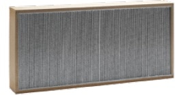
Wood Frame HEPA Filter. Image credit: NuAire
Using 7 years as a yardstick for 180% increase in pressure drop, the chart shown below was established by equaling the average life of the filter to percent increase in filter loading capacity or pressure drop.
While the chart is not linear, it is similar to that of a fan curve that enables additional loading of new filters and is likely to trail off with increased loading.
|
Percent Increase in Pressure Drop*
|
Average HEPA Filter Life (Years)
|
|
50%
|
3 Years**
|
|
100%
|
5 Years
|
|
180%
|
7 Years***
|
|
250%
|
10 Years
|
* Percent increase testing based on NSF/ANSI 49, Annex A.12 motor blower performance test methods
** Base line NSF requirement assuming more capacity is available
*** Industry standard requirement based originally on designed usage of AC PSC motor
New energy efficient motor technology - AC PSC versus new motor technologies
Nowadays, latest motor technologies are being integrated into most BSCs as a means to cut down energy usage. Cabinets are now being integrated with AC 3-phase, DC, and DC ECM motors, which provide better energy efficiency that range between 40% and 80%.
Yet, the majority of these motor technologies are not able to provide the inherent capabilities of the older AC PSC motor technology to boost RPM (torque) with increased filter loading [resistance].
These new generation of motors should be employed with a motor feedback control system or an airflow feedback loop control system. Both of these methods are valid, providing adequate airflow control to maintain the airflow of the cabinet within the recommended range of airflow containment performance.
The novel motor technologies with the required control capability can help reduce the system’s designed filter load capacity and at the same time fulfill the NSF requirement for blower/motor performance.
In other words, the original requirement of the NSF standard didn’t allow the fan (motor) speed control to be changed making sure the AC PSC motor was sized correctly with the fan using its inherent capability to increase rpm (torque) with more resistance or filter loading.
In order to offset the loading of HEPA filters, a built-in control system is required by the latest energy efficient motors to boost the RPM (speed). Using a control system or placing more requirements with its use is not limited by the NSF standard. Today’s standard still requires the total air delivery to decrease to 10% as a result of a 50% increase in the pressure drop that occurs across the filter.
However, the extra capacity of 180% that was almost ensured with the use of an AC PSC motor may no longer be present and should be checked. The manufacturer may provide this data within the BSC specifications, or product specifications for the BSC may point to the requirement.
Advantages of DC ECM motor technology
The filter loading capability was in fact increased by the new DC ECM motor technology, which was optimally integrated and implemented with a particular forward curved fan for each volumetric size or width of cabinet.
Additional capacity is offered by the DC ECM motor design in terms of the RPM of the motor, which provides as much as 250% increase in static pressure or pressure drop filter loading capacity. Energy costs have also been cut down by 50%, and the system is quieter in terms of vibration and noise.
When properly designed and developed into the BSC, the DC ECM motor affords the lowest life cycle cost with respect to filter load capacity, energy, and reliability.
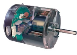
Ultra High Efficiency ECM Motor. Image credit: NuAire
Other considerations: size and type of supply and exhaust filters
HEPA filters
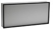
Metal frame HEPA filter. Image credit: NuAire
99.99% of particulates are trapped or retained by HEPA filters, while vapors, gases, fumes, and chemicals pass through the HEPA Filter Media. Similar to other media-type filters, the size or surface area of the filter as well as the number of air exchanges via the filter will eventually determine the effectiveness of the filter at retaining or trapping particles.
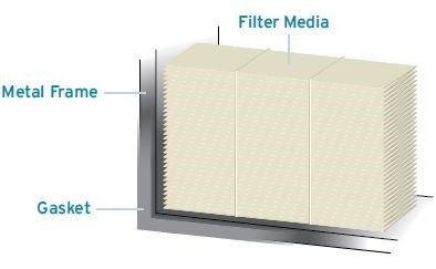
Image credit: NuAire
ULPA filters
More resistance in the cabinet’s airflow dynamics is generated by ULPA filters (99.999%) and this calls for multiple blowers or a larger blower to sustain the proper airflows. Compared to a HEPA filter, ULPA filters contain higher grade dense fiberglass media, are more costly, and have to be replaced more often. Compared to a HEPA filter, there is no advantage to using a ULPA filter for biological applications.
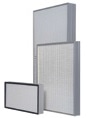
Image credit: NuAire
Controlling airflow
In a Class II, Type A2 BSC, airflow consists of both down flow for product protection and inflow for personnel protection. To ensure optimal containment performance, the airflow velocities of inflow and down flow are developed and balanced in a common plenum.
This common airflow plenum ensures that particles produced in the cabinet work zone are dragged into the blower and released inside the positive pressure common plenum for both supply and exhaust airflow distribution. Within the common plenum, distribution of particles is uniformly spread to reduce the generation of low/high airflow velocities within the work zone of the cabinet.
To stabilize the down flow to exhaust flow (inflow), an exhaust damper or choke is provided. Optimum performance of cabinet containment and long HEPA filter life are ensured through uniform particle distribution together with balancing down flow to exhaust flow (inflow).
Electronic airflow control system [motor speed controller]
In addition to providing the aforementioned benefits, the DC ECM motors can also be programmed to offer a continuous air volume while the HEPA filter is loaded with particulates. Moreover, the airflow control system can be further adjusted so that the highest containment performance together with the highest allowable HEPA filter use is achieved.
Advantages of NuAire
NuAire applies its technical know-how together with the best of the latest DC ECM technology to provide customers lower energy costs, better value, reduced vibration and noise, and longer filter life.
NuAire employs:
- the largest HEPA filters having the most pleats per square inch
- an internal exhaust damper
- an electronic airflow control system
- individually chosen and optimally determined forward-curved fans for each model width/size
The company is the only manufacturer to provide these features, which ensure the best quality, performance, service, reliability, and cost saving technologies.
Acknowledgements
Produced from materials originally authored by William Peters, Vice President of Engineering, NuAire.

About NuAire
Quality and Service
For more than 40 years, NuAire has been committed to bringing you the highest-quality, most dependable laboratory products on the market.
We are universally recognized as one of the world's leading providers of reliable equipment for the most demanding environments, including Biological Safety Cabinets, CO2 Incubators,Laminar Air Flow workstations, Ultra Low Temperature Freezers, Centrifuges,Animal Transfer Stations, Pharmacy Compounding Isolators, Polypropylene Fume Hoods, Polypropylene Casework, and a variety of complementary products and systems.
You can depend on our products to feature brilliant but practical design, and we pay keen attention to every step of the production process, from fabrication to assembly to thorough testing. As a NuAire customer, you can also rely on us for outstanding value and dependable service - the cornerstones of our reputation as the leading provider of laboratory products internationally.
Committed to Your Success
At NuAire, we create our high-quality products with your success in mind. This means that if you purchase a piece of laboratory equipment from us, we want you to be completely happy while using it.
NuAire will work hand-in-hand with you in order to ensure that your experience using our product meets your standards, and if you encounter any issues or difficulties along the way, we'll help you work through them until you are 100% satisfied. Our philosophy is that we succeed only when you succeed - and we are committed to working hard to ensure you achieve your goals.
Made in America
At NuAire, you can depend on us for being a company that is "Made in America." Our Airflow Products, CO2 Incubators, and Polypropylene Products are manufactured at three locations in Minnesota.
With over 300,000 square feet of manufacturing space, including a state-of-the-art robotic sheet metal facility, NuAire is able to provide employment to 300 Minnesota families and 60 North American sales representatives, and our manufacturing labor is 100% American.
We also purchase our materials from over 500 American vendors, each operating principally in the United States. More than 60% of the raw materials, parts, and supplies for our products originates in the U.S., and an average of 20-30% of the stainless steel flats we use are made from recycled metal.
International Leader
While NuAire is an American company, we also have several international business partnerships, which allow us to better serve you, the global laboratory community. NuAire recently started manufacturing a line of Biological Safety Cabinets in China in order to supply products to the Asian markets via Techcomp, Ltd., a publicly traded Chinese company.
In 2014, NuAire founded an international partnership with Hitachi Koki in order to supply high performance centrifuges to the North American market. NuAire can now provide customers with the sales and service of Hitachi High Speed, Ultra, and Micro Ultracentrifuges.
With several other partnerships with a variety of European and Asian companies, we have sold over 100,000 biological safety cabinets to customers in 150 countries and have equipment located on all 7 continents.
Sponsored Content Policy: News-Medical.net publishes articles and related content that may be derived from sources where we have existing commercial relationships, provided such content adds value to the core editorial ethos of News-Medical.Net which is to educate and inform site visitors interested in medical research, science, medical devices and treatments.