In conventional centrifugation rotors, material processing involves a number of tedious steps, which need to be repeated until the whole sample has been processed.
If the amount of material to be processed is large, its rate of sedimentation low, the deceleration/acceleration time of the rotor long, and the capacity of the rotor small, then conventional processing of large volumes of material will be labor-intensive and take up a significant amount of time.
One process that reduces material processing time is continuous flow centrifugation. In this process, large volumes of material can be centrifuged at high centrifugal forces without having to fill and decant a large number of centrifuge tubes or frequently stop and start the rotor.
For instance, the continuous flow method can process 10L of liquid containing 500S particles in 4h or less, depending on the type of rotor chosen. However, the same operation would take 12 to 21 hours with conventional batch-type centrifugation.
The combination of high throughput and high centrifugal force makes continuous flow processing especially useful for:
- Pelleting of subcellular fractions
- Sedimentation of bacteria
- Large-scale collection of viruses for commercial vaccine preparation or for research purposes
Nonetheless, continuous flow centrifugation does not necessarily need to be confined to biomedical applications and should be considered when any type of particles with sedimentation coefficients of 50 S or more need to be routinely separated from fluid volumes of 2L or more. Continuous flow rotors considerably reduce material processing time for two reasons:
- Their capacities are large, meaning they do not need to be stopped and started as frequently as conventional rotors do. As a result, sample handling time is reduced and the time spent waiting for rotor deceleration and acceleration between the runs is reduced.
- Their short path lengths minimize the overall pelleting time. Therefore, they efficiently pellet solids out of a sample stream and facilitate a rapid flow of material through the rotor.
Qualifying the Sample
Continuous flow rotors offer the most benefit over conventional rotors if the sample possesses the following properties:
- A low solid:liquid ratio (5 to 15%). If this ratio is above 15%, the rotor is likely to be over efficient.
- The particles’ sedimentation coefficient is more than 50 S
Continuous Flow Operation
The CF-32 Ti and JCF-Z continuous flow rotors from Beckman Coulter function on a batch-processing, continuous flow basis.
This means a batch of particle-containing liquid constantly flows into the rotor, which is running at the chosen operating speed.
Particles sediment out of the flowing stream, which then emerges as a particle-depleted effluent and this continues until the rotor’s particle-containing capacity is reached or until the starting material (the sample) is fully processed.
Therefore, the concentration of the particles the sample contains, as well as its volume govern the amount of starting material that can be managed in a single run.
The particle-depleted effluent, the sediment, or both can be collected, just as one collects the sediment, supernatant, or both, following differential centrifugation in conventional swinging bucket or fixed-angle rotors.
The JCF-Z and CF-32 Ti rotors consist of a bowl, a solid core within the bowl, and a lid, as shown in Figure 1.
Radial channels for the flow of liquids move through the core. On the top surface of the core, are four milled slots, through which liquids flow for loading and sometimes unloading the rotor.
The rotating seal assemblies allow the continuous flow mode of operation, by enabling the fluid-bearing lines to stay fixed to the rotors during operation.
These seals prevent the sample from being exposed to environmental air, thereby minimizing potential contamination of the sample. For loading and unloading, the flow of fluid through the rotor can be reversed by switching the fluid lines.
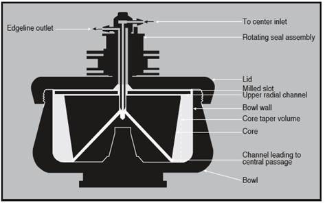
Figure 1. Cross-section of a continuous flow rotor. Image credit: Beckman Coulter
The rotor is prepared for centrifugation while it spins at a low speed. Cushion, buffer solution, or discontinuous layers of sucrose or another gradient material are pumped in through the edge line.
The rotor is then accelerated to operating speed, the fluid lines are switched and the particle-containing liquid is routed through the center inlet of the seal using the same pump. It is then passed via the channels in the rotor core to the bottom of the rotor bowl.
Unwanted foaming is virtually eliminated by the direct, sealed pathway (Figure 2). As the flowing liquid travels upward along the core taper and towards the top of the bowl, particle sedimentation towards the bowl wall occurs.
The particle-depleted effluent moves through the upper radial channel and exits the rotor via the outlet line in the seal assembly.
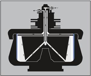
Figure 2. Continuous flow centrifugation. The arrows on the diagram indicate the direction of liquid flow during continuous flow operation. The sample is pumped in through the center inlet to the bottom of the core. The flow rate is adjusted so that the particles of interest have time to become trapped in the gradient or cushion (or pelleted on the rotor wall) during the time required to move from the bottom of the core to the upper radial channel. Image credit: Beckman Coulter
Separation Techniques
It is vital to concentrate the particles in one of three ways:
- By banding in a gradient
- By pelleting onto the rotor bowl wall
- By sedimentation onto a cushion of a dense liquid such as sucrose
The last two techniques are most useful for recovering the particle-depleted effluent or harvesting the particles. Banding will give optimum results whenever a particle has to be separated from contaminants of varied densities.
Pelleting and Clarifying
Pelleting is the fastest continuous flow technique and capable of handling large volumes of starting material. It is suitable for collecting particles that will not be damaged by being pressed against the rotor wall.
Sedimenting onto a Cushion
Certain particles may lose biological activity if pelleted. Such particles can be sedimented onto a cushion of a dense solution such as sucrose. The cushion can be used in situations where it is more convenient to collect the particles in solution instead of having to scrape a pellet from the wall of the rotor.
The rotor’s particle-bearing capacity will be reduced by the presence of a cushion. For this kind of run, the rotor is loaded while operating at reduced speed (Figure 3).
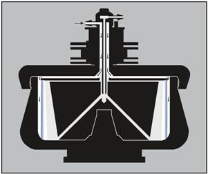
Figure 3. Loading a cushion or gradient. The arrows indicate the direction of liquid flow during loading. With the rotor turning at low speed, the cushion or gradient (light end first) is pumped in through the edge line. Air is displaced through the center inlet. The cushion or gradient is held against the rotor wall by centrifugal force. Image credit: Beckman Coulter
Banding in a Gradient
This is the most common technique used for virus purification. A pre-formed linear gradient is not required due to the short sedimentation path length present in the continuous flow rotors.
Step concentrations will diffuse sufficiently to become linear during the process of loading and acceleration.
Selecting a Flow Rate
The selection of operating speed and flow rate are determined by the sedimentation coefficient of the particles to be collected. Small particles need either a high centrifugal force field or more time to sediment than larger particles.
The goal is to choose an operating speed that will produce a high enough centrifugal force to sediment the target particles, and a low enough flow rate to provide time for those particles to sediment out of the flowing stream before it exits the rotor.
Rotors, Cores, and Their Uses
Beckman Coulter offers two continuous flow rotors – the CF-32 Ti rotor and JCF-Z rotor. The latter operates at a maximum speed of 20,000 rpm and is compatible with select Avanti series centrifuges.
It includes three interchangeable cores for continuous flow operation and two for zonal runs. These include:
- Standard Core
- Large Pellet Core
- Small Pellet Core
- Reorienting Gradient Core
- Zonal Core
Here, only the continuous flow cores are discussed. Figure 4 shows an image of the JCF-Z rotor and figure 5 shows the rotor’s continuous flow cores. The CF-32 Ti rotor has a single core, as shown in figure 6, and is designed for continuous flow operation only. Its maximum speed is 32,000 rpm and it can be applied in the Optima X series ultracentrifuges and most Model L series ultracentrifuges.
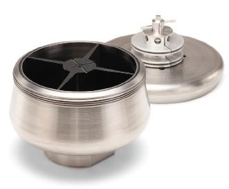
Figure 4. JCF-Z continuous flow rotor. Image credit: Beckman Coulter
Figure 5. JCF-Z continuous flow rotor and cores. Image credit: Beckman Coulter
Figure 6. CF-32 Ti continuous flow rotor and core. Image credit: Beckman Coulter
The JCF-Z and CF-32 Ti rotors both have lids and bowls made of titanium. The Noryl-based cores can be safely used with most of the common density gradient buffers and media. All but the JCF-Z Small Pellet Core are tapered and have four removable Noryl baffles attached that stabilize the liquid inside the rotors during operation.
These baffles divide the interior of the rotor. The total capacity of the rotor is determined by the amount of space between the bowl wall and the core. Of this total capacity, a certain amount can be occupied by gradient, pellet layer, or cushion at the periphery of the rotor.
Taper volume refers to the remaining capacity, adjacent to the core. This is the area the starting material flows through and where sedimentation onto the cushion or rotor wall, or into a gradient occurs. Table 1 summarizes the specifications of the different rotor-core configurations.
Table 1. Beckman Coulter Continuous Flow Rotors and Cores
|
Specifications
|
CF-32-Ti
|
JCF-Z
|
|
Standard Core
|
Small Pellet Core
|
Large Pellet Core
|
|
Maximum Rotor Speed
|
32,000 rpm
|
20,000rpm
|
20,000rpm
|
20,000rpm
|
|
Maximum Force at Bottom of Core
|
86,100g
|
32,000g
|
25,000g
|
23,000g
|
|
Maximum Force at Top of Core
|
91,950g
|
34,000g
|
25,000g
|
25,000g
|
|
Maximum Force at Rotor Wall
|
102,000g
|
39,900g
|
36,300g
|
39,900g
|
|
Total Rotor Capacity
|
430mL
|
660mL
|
240mL
|
1250mL
|
|
Maximum Pellet Capacity
|
330mL
|
400mL
|
204mL
|
800mL
|
|
Maximum Flow Rate—Standard Seal Assembly
|
9L/h
|
45L/h
|
45L/h
|
45L/h
|
|
Maximum Flow Rate—High Flow Seal Assembly
|
—
|
100L/h
|
100L/h
|
100L/h
|
|
Maximum Permissible Density of Contents at Maximum Speed
|
1.20g/mL
|
1.45g/mL
|
1.45g/mL
|
1.45g/mL
|
|
Permissible pH Range for Liquids
|
pH 4–10
|
pH 4–10
|
pH 4–10
|
pH 4–10
|
JCF-Z Rotor
Fitted with one of its continuous flow cores, the JCF-Z rotor is suitable for sedimentation of bacteria, larger subcellular particles such as mitochondria and membranes, and viruses or other particles with sedimentation coefficients of 500 S and higher.
The JCF-Z with the Standard Core generates 39,900 x g at the inner surface of the bowl wall and 32,000 x g at the core bottom when operating at its maximum speed of 20,000rpm.
It can be operated at flow rates between 3 and 45L/h. For handling very large volumes where higher flow rates would be expedient, a high-flow seal assembly is available which makes it possible to process up to 100L/h.
This rotor can be applied in select Avanti centrifuges, without modification. These centrifuges are refrigerated, but the rotor should be pre-cooled whenever temperature control of the sample is important.
In such a situation, the fluids to be pumped through the rotor should also be pre-cooled because they will become warmed to some degree while moving through the pump tubing and the seal assembly.
Sample reservoirs should be stored either in a refrigerated water bath or in ice and tubing lines should be kept as short as they can be.
The quantity of the anticipated pellet or the need to sediment into a step gradient or onto a cushion governs which of the three JCF-Z continuous flow cores should be used.
The total capacity of the standard core is 660 mL and of this volume, approximately 400 mL can be taken up by the cushion, step gradient, or pellet. The core is suitable for pelleting against the rotor wall or a cushion, banding of particles, or clarifying liquids.
The total capacity of the large pellet core is 1250 mL, of which about 800mL can be taken up by the pellet. It is suitable only for pelleting. This core is very suitable for centrifuging fluids containing a large amount of solids, and a solid-to-liquid ratio as high as 1:2 can be processed.
The total capacity of the small pellet core is 240 mL, of which approximately 200 mL can be taken up by the pellet. It is designed for the processing of large quantities of material with a low solid-to-liquid ratio.
To reduce re-suspension of sedimented material, this core features six separate cavities, with each having removable, canoe-shaped containers that the pellets collect in. This core is also designed only for pelleting.
There are also two other interchangeable cores in the JCF-Z rotor, for zonal separations: the Zonal Core and the Reorienting Gradient Core.
CF-32 Ti Rotor
The CF-32 Ti rotor can be used to concentrate particles that range widely in size. Owing to its high speed, it is particularly suitable for banding viruses or other small particles with sedimentation coefficients down to 50S.
At the maximum speed, it produces 102,000 x g and 86,100 x g at the inner surface of the bowl wall and core bottom, respectively. It operates at flow rates of up to 9L/h.
The total capacity of this rotor is 430 mL, of which approximately 330mL can be taken up by the pellet. This capacity is reduced when a step gradient or cushion is used, either of which will take up around 300mL.
The ultracentrifuges, which hold the CF-32 Ti rotor, provide refrigerated operation. Since the seal assembly of the CF-32 Ti rotor is equipped with a stainless steel water jacket, normal temperatures can be maintained at the seal at much lower flow rates compared to in the JCF-Z rotor.
A tap water supply can be used for the water jacket, unless a temperature of 10ºC or lower is needed at the seal assembly. Then, a pump and water cooler should be used and the rotor and starting material should also be precooled.
Other Equipment Required
As well as either the CF-32 Ti and JCF-Z rotor and its respective centrifuge, a peristaltic pump is needed for introducing step gradients or cushions into the rotor and also for pumping starting material.
This pump needs to be able to operate against a back pressure of 138kPa. Also, a pressure gauge for checking flow rates between the seal assembly and the pump may be helpful.
A flow-through photometer is also helpful for monitoring the effluent to observe cleanout of the sample during pelleting and for detecting banded material during the unloading of gradients or cushions.
Tubing lines in and out of the flow cell should be of the same diameter as the rotor tubing. Additionally, a fraction collector may be useful.
Sample and effluent reservoirs would of course be needed, along with accessories needed for refrigeration. Figures 7 and 8 show the typical equipment setups.
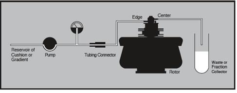
Figure 7. Equipment arrangement for loading and unloading cushion or step gradient. Image credit: Beckman Coulter
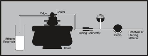
Figure 8. Equipment arrangement during continuous flow centrifugation. Image credit: Beckman Coulter
Author acknowledgement
Created from content authored by Mel Dorin and Judy Cummings, Beckman Coulter, Inc., Indianapolis, IN, USA.
 About Beckman Coulter
Beckman Coulter develops, manufactures and markets products that simplify, automate and innovate complex biomedical tests. More than a quarter of a million Beckman Coulter instruments operate in laboratories around the world, supplying critical information for improving patient health and reducing the cost of care.
Sponsored Content Policy: News-Medical.net publishes articles and related content that may be derived from sources where we have existing commercial relationships, provided such content adds value to the core editorial ethos of News-Medical.Net which is to educate and inform site visitors interested in medical research, science, medical devices and treatments.