Sponsored Content by LittelfuseReviewed by Olivia FrostOct 14 2025
Continuous Glucose Monitors (CGMs) are transforming diabetes management by providing a constant stream of glucose readings, thereby eliminating the need for frequent finger sticks. These compact, wearable medical devices are helping patients live more independently while enabling healthcare professionals to make more timely, data-driven treatment decisions.
As part of the rapidly growing field of connected healthcare, CGMs exemplify how electronic innovation can improve medical outcomes while reducing system-level costs. But, for CGM designers, the path to innovation involves balancing tight power budgets, safety requirements, and ultra-compact form factors while maintaining reliable wireless connectivity and precise sensing performance.
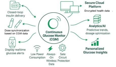
Figure 1. Connected drug delivery system example. Image Credit: Littelfuse
CGMs in the broader healthcare ecosystem
This article explores the critical electronic protection and sensing design requirements for CGMs and the Littelfuse technologies that support their development. Figures 2 and 3 illustrate a simplified CGM system block diagram, highlighting key protection and activation components used in this type of wearable medical device.
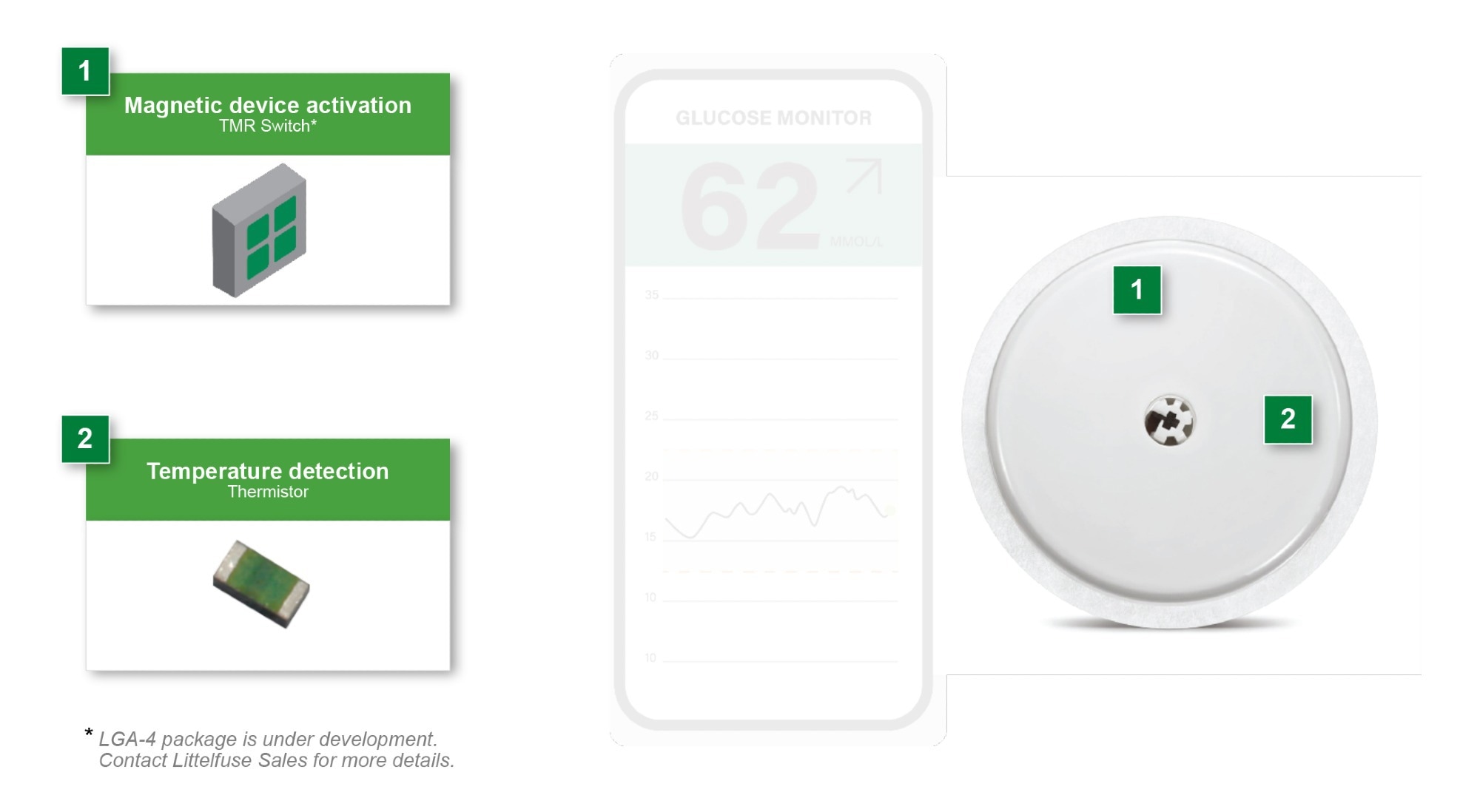
Figure 2. Continuous Glucose Monitor (CGM). Image Credit: Littelfuse
CGMs measure glucose levels in interstitial fluid through a sensor inserted just beneath the skin. The system typically includes an analog front-end (AFE) to condition the sensor signal, a microcontroller (MCU) with Bluetooth® Low Energy or proprietary wireless communication, memory storage, and a small rechargeable or primary battery. The readings are transmitted to an insulin pump, smartphone, or cloud platform for further processing and visualization.
CGMs are central to modern diabetes care, especially for patients with type 1 diabetes and those requiring intensive insulin therapy. However, they are increasingly being prescribed for a broader population, including type 2 diabetics, pregnant women with gestational diabetes, and individuals with high-risk prediabetic conditions.
The benefits are compelling - reduced glycemic variability, improved Hemoglobin A1c (HbA1c) levels, and lower incidence of hypoglycemia - all of which translate to better patient outcomes and reduced long-term healthcare costs. The CGM market is expected to grow significantly over the next decade, supported by improved sensor technology, insurance coverage, and global health policy initiatives.
As CGMs evolve, the importance of robust, low-power, and miniaturized electronics becomes increasingly critical to ensure accurate data capture, device uptime, and user comfort.
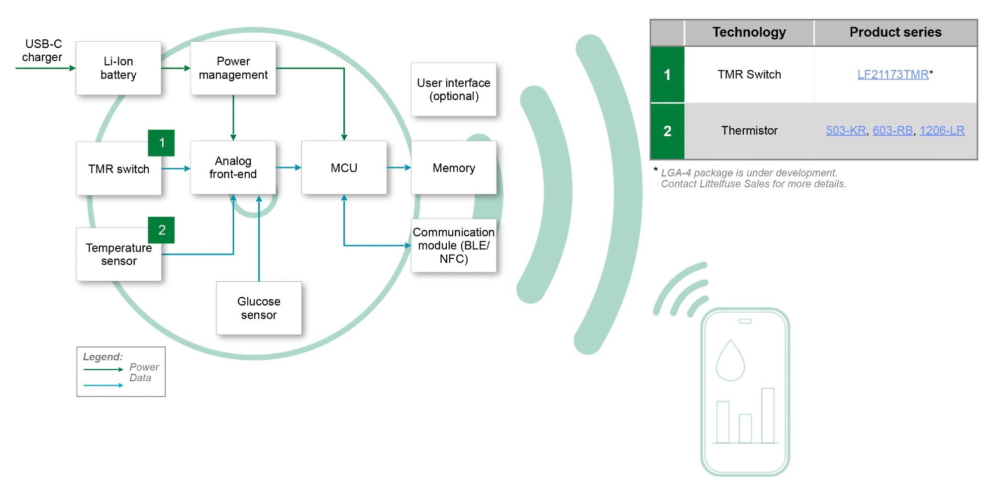
Figure 3. CGM system block diagram & recommended components. Image Credit: Littelfuse
Figure 3 shows a representative block diagram demonstrating glucose sensor input, analog front-end (AFE), power management, microcontroller with wireless connectivity, memory, and user interface circuits. Protection and sensing components, including TMR switches, ESD protection, TVS diodes, and thin-film fuses, are integrated throughout the system.
Engineering challenges in CGM design
CGMs must perform reliably under continuous operation, often for 7 to 14 days on a single charge or disposable power source. This requirement imposes tight power and size constraints on every component in the system. The device must also function under a variety of environmental conditions, including exposure to sweat, motion, and temperature fluctuations, all while adhering to strict medical safety and EMC regulations.
Key design requirements include:
- Ultra-low power consumption: Even microamp-level leakage can compromise battery life
- Miniaturization: Board real estate is minimal, especially for patch-style designs
- Overcurrent protection: Short-circuit faults or component failures must be isolated quickly to prevent overheating or battery damage
- Transient voltage protection: Electrostatic discharge (ESD) and EMI events can corrupt sensor readings or damage ICs
- Reliable activation mechanisms: Contactless power-on and interface switches reduce mechanical wear and improve usability
- Regulatory compliance: Devices must meet stringent international safety, EMC, and reliability standards
Magnetic activation using TMR switches
A growing number of CGM devices now employ magnetic switches to activate or reset the device. These magnetic switches provide a contactless alternative to mechanical push buttons, which can degrade due to wear or exposure to moisture. In CGMs, magnetic switches are often used to detect when the device has been adhered to the skin or removed from its packaging tray, triggering power-on or configuration routines. Options for magnetic switch detection include reed relay switching, Hall sensor switching, and tunnel magnetoresistance (TMR) switching.
Littelfuse Tunnel Magnetoresistance (TMR) switches are a strong fit for this use case. These solid-state devices operate in the nanoamp-to-low microamp current range, allowing activation features to be implemented without compromising the system’s power budget.
TMR sensors are naturally resistant to vibration, contamination, and humidity, and they’re rated for tens of billions of switching cycles. Compared to other options, they strike an ideal balance: reed relays, while drawing no current, are bulkier, more shock-sensitive, and less responsive. Hall sensors consume the most current and are also physically larger than TMR sensors. TMR technology stands out for offering compact size, low power consumption, high sensitivity, and durability.
The Littelfuse LGA-4 TMR switches are especially compact, housed in a 1.5 mm square surface-mount package. The low-speed version draws just 160 nA during operation, with a maximum current of 1.9 µA and a sleep mode requirement of only 148 nA. These omnipolar switches respond to either magnetic pole and offer excellent sensitivity, with switching triggered by a magnetic flux density as low as 9 Gauss.
TMR switches also provide excellent design flexibility. With no moving parts, no contact bounce, and ultra-low power draw, they help extend device life and minimize the risk of accidental activation. This makes them particularly well-suited for the healthcare wearables market, where hygiene, longevity, and reliability are essential.
Circuit protection for always-on reliability
Accurate glucose monitoring depends on clean signals and safe power, both of which are protected by the right circuit protection components. Here are some key Littelfuse device categories that help make CGM designs safer and more reliable:
Thermistors
Temperature monitoring in a CGM is used for several important functions: ensuring electronic safety, protecting the user, and enabling accurate sensor performance. Monitoring skin temperature trends can detect sensor site inflammation. Temperature information at the skin surface enables compensation for temperature-dependent glucose oxidase reaction rates and sensor temperature-dependent properties.
Littelfuse compact surface-mount thermistors, such as the KR series thermistors, sense temperature with 5 % accuracy. They mount on hybrid substrates, integrated circuits, or printed circuit boards. Models offer varying resistance ranges to accommodate CGM circuit designs. Their compact size, measuring 1.6 mm x 0.8 mm with a thickness of 1.0 mm, makes them an excellent choice for use in CGMs.
ESD protection diodes
CGMs are handled by patients, clinicians, and manufacturers, with each interaction introducing potential ESD hazards. ESD protection diodes such as those in the Littelfuse SP100x, SP300x, and SESD series are optimized for IEC 61000-4-2 compliance and protect sensitive inputs and outputs, including BLE transceiver front-end circuitry and sensor I/O lines. Models can withstand ESD strikes from ±8 kV to as much as ±30 kV.
Ultra-low capacitance models provide transient voltage protection while preserving high-speed signal integrity. The capacitance of the various models can range from 0.13 pF to 30 pF, while their small form factors make them easy to integrate into compact PCB layouts. TVS Diodes with reverse standoff voltages of 6 V and lower are commonly used in CGM circuits to shield critical MCU and RF pathways.
TVS diodes
Transient voltage suppressor (TVS) diodes offer robust protection against induced external transients resulting from electromagnetic interference generated by mobile phones, RFID readers, and medical equipment.
Littelfuse SPxx bidirectional TVS diodes and SMBx TVS diodes provide robust ESD protection for sensitive analog front-end circuitry used in CGMs. These components have low leakage currents of 1 µA or lower. They can clamp transients at voltages under 20 V.
The TPSMC series TVS diodes are another series with under 1 ps response time, along with low leakage current, high surge-handling capabilities, and compact DO-214 packaging. In addition to protecting analog front-ends, these components are often used to protect power inputs and battery management interfaces.
Thin-film and nano fuses
Overcurrent protection is crucial for isolating faults and safeguarding the battery in the event of failure. Littelfuse NANO2®, PICO®, and thin-film fuse families are specifically designed for compact applications that require high interrupt ratings and can have fast-acting responses. These fuses can have time-delay or fast-acting models. They are typically installed in series with battery charging circuits, VBUS rails, or between power converters and their downstream loads. Time-delay models can be used where inrush protection is needed, while fast-blow versions protect against rapid short-circuit events.
Resettable fuses
When resettable protection is a design requirement, the Littelfuse Low Rho series surface-mount polymer positive temperature coefficient (PTC) fuses are a strong fit. These fuses have exceptionally low internal resistance, helping to reduce power loss in the system. Some models can handle hold currents up to 1 A and come in compact 0402 packages with a maximum height of just 6 mm.
Benefits of integrated protection and sensing
Well-designed CGM electronics employ a combination of activation, protection, and power management strategies to ensure uninterrupted operation and patient safety. Utilizing Littelfuse components helps simplify system certification, reduce development time, and enhance end-user confidence.
By integrating magnetic sensing and circuit protection into the core design, CGM engineers can:
- Improve mechanical robustness by eliminating moving parts
- Extend device uptime through low-standby-current components
- Meet global medical device safety and EMC standards
- Increase patient compliance through reliable user experiences
All of these improvements support better clinical outcomes and lower support costs over the product lifecycle.
Compliance with relevant medical and EMC standards
CGM systems must comply with a range of global standards to ensure safety, performance, and regulatory approval. These include the regulatory standards shown in Table 1.
Table 1. Applicable standards for CGMs. Source: Littelfuse
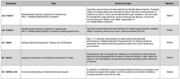
Littelfuse protection and sensing devices are designed with these compliance frameworks in mind and are backed by complete documentation and technical support for medical applications.
Conclusion
CGMs are a cornerstone of modern diabetes care and are expanding into broader health and wellness markets. These body-worn medical devices demand sophisticated engineering to ensure accuracy, uptime, and usability in a compact, patient-friendly format.
Littelfuse helps enable safe and efficient CGM designs with specialized components for ultra-low-power magnetic activation, circuit protection, and transient suppression. With growing regulatory pressure and user expectations, using proven components from a trusted supplier accelerates time-to-market and improves device performance.
By integrating technologies such as TMR magnetic switches, ESD/TVS protection diodes, and medical-grade fuses, engineers can deliver CGMs that meet today’s toughest challenges, empowering patients with safer, more connected, and longer-lasting health monitoring solutions.
Acknowledgments
This article is based on materials originally authored by Dr. Marco Doms from Littelfuse, Inc.
References
- Littelfuse. (2025). Littelfuse Catalogs. (online) Available at: https://electronicscatalogs.littelfuse.com/Circuit-Protection-Product-Selection-Guide/1/.
- Littelfuse. (2025). Littelfuse Catalogs. (online) Available at: https://electronicscatalogs.littelfuse.com/Sensing-Products-Selection-Guide/30/.
- Portable Medical Devices Protection Quick Reference Guide
- C&K Components, Inc. (2022b). Switch Solutions for Medical Applications. MaRKETFLYER. Available at: https://www.ckswitches.com/media/3693/ck_medical-flyer.pdf.
- Use of Low Resistivity Surface Mount PPTC in Li-ion Polymer Battery Packs Application Note
About Littelfuse
Littelfuse is a diversified industrial technology manufacturing company empowering a sustainable, connected, and safer world. Across more than 20 countries, and with approximately 16,000 global associates, we partner with customers to design and deliver innovative, reliable solutions. Serving over 100,000 end customers, our products are found in a variety of industrial, transportation, and electronics end markets - everywhere, every day. Headquartered in Chicago, Illinois, United States, Littelfuse was founded in 1927.
Sponsored Content Policy: News-Medical.net publishes articles and related content that may be derived from sources where we have existing commercial relationships, provided such content adds value to the core editorial ethos of News-Medical.Net which is to educate and inform site visitors interested in medical research, science, medical devices and treatments.