Spectrophotometers and microplate readers use photomultiplier tubes (PMT) to detect luminescence and fluorescence signals.
These processes see photons emitted at specific wavelengths. First, the PMT converts photons into electrons, then amplifies the signal so it can be detected and expressed in relative fluorescence/luminescence Units (RFU, RLU).
This article explores the use of PMT with xenon flash-lamp-based microplate readers, leveraging the unique, patented AutoPMT™ data normalization functionality from Molecular Devices.
PMT principles
The PMT counts the photons that strike the photocathode, converting them into electrons. The electrons are first deflected so they hit the primary dynode, then amplified over a series of subsequent dynodes (Figure 1).
The number of generated electrons is proportional to the number of incoming photons. The number of generated electrons increases with the voltage or gain applied to the PMT.
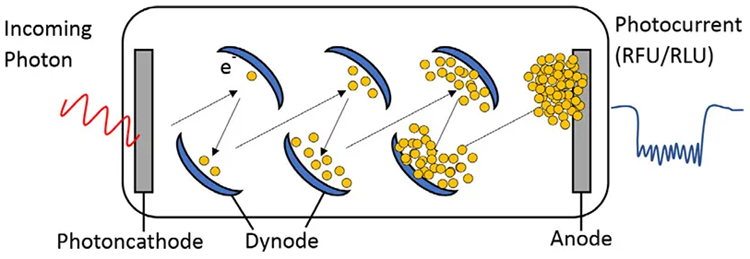
Figure 1. Diagram of a photomultiplier tube (PMT). PMTs convert photons into electrons and amplify the signal. Image Credit: Molecular Devices UK Ltd
Material and methods
- SpectraMax M5e Multi-Mode Microplate Reader
- 96-well plate
- 10 μM fluorescein in 1x phosphate-buffered saline (PBS)
In order to demonstrate the various aspects of PMT gain and data normalization, an initial concentration of 10 μM fluorescein in 1x PBS was employed for the standard curve. This facilitated a final concentration of 0.1 nM fluorescein.
The samples were plated in triplicate, with PBS included as a blank.
The plate was read four times using the high, medium, low, or auto PMT settings. This was performed at an excitation wavelength of 485 nm and an emission wavelength of 525 nm. A 515 nm cutoff filter was also used.
The SpectraMax M5e Microplate Reader was used to perform all endpoint measurements. The SoftMax® Pro 7.1 software was used to acquire and display RFUs.
PMT gain adjustment
The PMT gain should be adjusted in line with the signal generated by the well to ensure the assay offers optimal sensitivity and dynamic range.
High sample concentrations emit more photons and necessitate a lower PMT gain or voltage, while low sample concentrations emit few photons and necessitate a higher PMT gain or voltage.
The PMT gain for most plate readers or spectrophotometers is set to a fixed value, manually or automatically, before the entire plate is read.
Molecular Devices’ SoftMax Pro data analysis software offers a range of pre-defined PMT gain options, for example, the automatic, high, medium, or low settings, as well as a manual option (Figure 2). These options vary depending on the plate reader model.
Choosing the Manual PMT gain option allows the user to enter a PMT gain value between 500 and 1000 volts for the SpectraMax i Series Multi-Mode Microplate Readers (i3x, iD3, and iD5) or between 200 and 1000 volts for the SpectraMax M Series and the Gemini microplate readers.
The high, medium, and low PMT gain options each provide a nominal dynamic range of three decades. This allows a voltage setting to be selected that is low enough to avoid PMT saturation but high enough to maximize sensitivity (Figure 3).
The optimum PMT gain is the highest value that avoids PMT saturation while maximizing the number of signal samples. Should the PMT be unable to detect the signal due to saturation, the SoftMax Pro and the exported data will show the result as ‘#SAT’. Reading lower-concentration samples with a low PMT setting will reduce sensitivity at low signal intensities (Figure 3).
Users are advised to select the automatic PMT gain option if the range of fluorescence intensities within a single microplate is greater than three to four orders of magnitude.
The Automatic PMT gain option uses Molecular Devices’ patented AutoPMT™ feature. This feature is unique to the company’s M series, Flex, i3x, iDx, and Gemini microplate readers.
This allows a broad range of fluorescence signal intensities within the same plate to be read in a single read. The optimal gain for each well is automatically calculated by the AutoPMT™.
A pre-read of the microplate is performed at high PMT. If this results in no wells saturating, the reads are completed at high PMT. Should any wells saturate, however, these wells will be read at medium PMT. If any wells still saturate at medium PMT, they will be read at low PMT.
In AutoPMT™ mode, it is possible to automatically obtain a six- or higher-decade dynamic range in a single plate read (Figure 3).
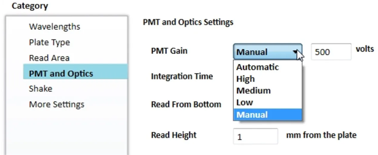
Figure 2. Adjustable PMT Settings in SoftMax Pro. Image Credit: Molecular Devices UK Ltd
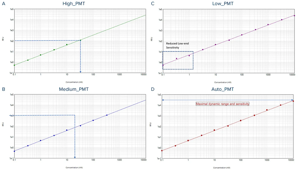
Figure 3. Standard curve with pre-defined PMT settings compared to AutoPMT™. A. High PMT gain shows a quick saturation of the PMT at a concentration of 33 nm. B. Medium PMT gain shows saturation at a concentration of 333 nM; PMT Low can read the full concentration range but loses sensitivity at low concentration. D. Automatic PMT allows maximal dynamic range with high sensitivity at all concentrations. Image Credit: Molecular Devices UK Ltd
Data normalization
Reading the same samples with different PMT gains results in the unnormalized RFU values differing for the same sample and the generation of different standard curves (Figure 4A).
Samples read at a higher PMT gain will report higher RFU values than when read at a lower PMT gain. The presence of different RFU values introduces difficulties when comparing data from the same assay, depending on the concentration range used on the plate. RFU must be normalized to be independent of the voltage.
Microplate readers from Molecular Devices leverage a PMT calibration coefficient determined by measuring a fluorescent sample of known intensity for signal normalization. The measured sample is fixed within the instrument.
Full and automatic data normalization is provided by the SoftMax Pro software (Figure 4B).
No further data adjustment is necessary following the measurements. This approach saves time and is easy to use, as it implements fast, automatic normalization without requiring multiple measurements across different PMT settings. Collected data is normalized simultaneously to ensure full linearity across the maximum dynamic range.
An important advantage of this normalization is evident when working with kinetic assays, where signal intensities change from day to day, over time, or under varying assay conditions. For kinetic reads, it is important that the PMT settings be fixed. It is also advisable to start with a medium PMT, adjusting it to a low PMT if some wells saturate, or to a high PMT if the signal from every well is found to be low.
Kinetic curves and final results can be compared regardless of the PMT gain used across experiments because the collected data is normalized simultaneously.
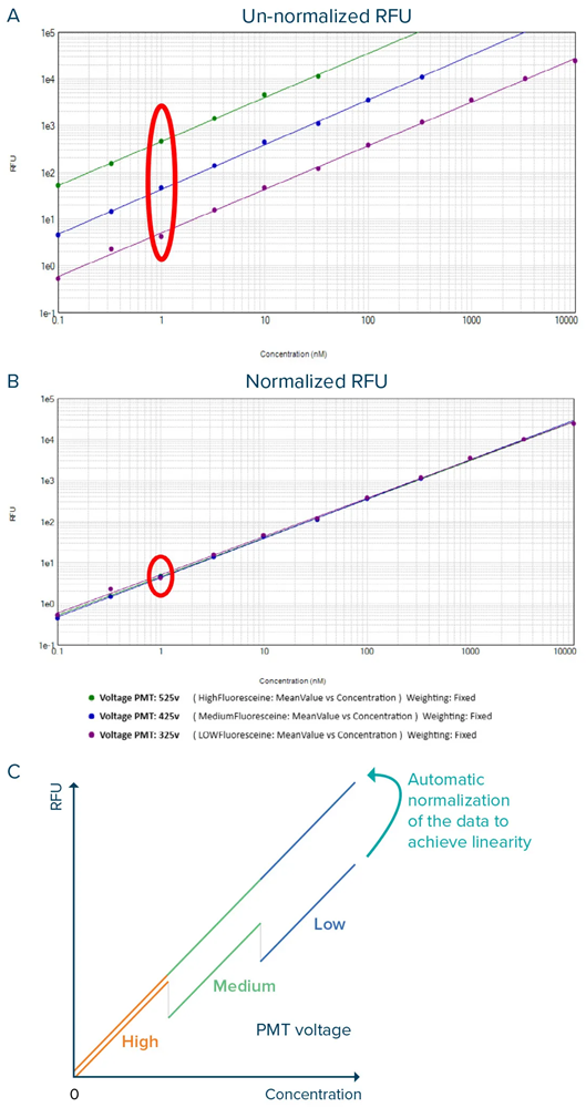
Figure 4. Standard curve read at three different PMT gains (325 V, 425 V, and 525 V) without data normalization (A. Un-normalized RFU) and with data normalization (B. Normalized RFU). C. Graph showing the data normalization for each PMT voltage when the Automatic PMT option is used. Image Credit: Molecular Devices UK Ltd
Conclusion
It is well known that the sensitivity of the PMT and the lamp, and the efficiency of the monochromator, can cause results to vary slightly from day to day and instrument to instrument.
Molecular Devices’ range of AutoPMT™-supporting microplate readers compensates for these factors by offering robust instrument design, streamlined calibration, and full RFU normalization to deliver high-quality fluorescence data and optimal reproducibility over time.
About Molecular Devices UK Ltd
Molecular Devices is one of the world’s leading providers of high-performance bioanalytical measurement systems, software and consumables for life science research, pharmaceutical and biotherapeutic development. Included within a broad product portfolio are platforms for high-throughput screening, genomic and cellular analysis, colony selection and microplate detection. These leading-edge products enable scientists to improve productivity and effectiveness, ultimately accelerating research and the discovery of new therapeutics. Molecular Devices is committed to the continual development of innovative solutions for life science applications. The company is headquartered in Silicon Valley, California, with offices around the globe. For more information, please visit www.moleculardevices.com.
Sponsored Content Policy: News-Medical.net publishes articles and related content that may be derived from sources where we have existing commercial relationships, provided such content adds value to the core editorial ethos of News-Medical.net, which is to educate and inform site visitors interested in medical research, science, medical devices and treatments.